Minimum Bending Radius (Static Conditions)
The following formula can be used to determine the minimum values for the radii to which such cables may be bent for permanent training:
MBR = OD x M
Where:
MBR = Minimum radius of bend (in)
OD = Outside diameter of cable (in)
M = Diameter multiplier (Please see tables on the next page(s))
Note: The above calculation applies to STATIC conditions ONLY. Please reference the DYNAMIC conditions section below and the Sidewall Bearing Pressure section for the minimum bending radius of cable in motion.
Minimum Bending Radius (Dynamic Conditions)
The following formula can be used to determine the minimum values for the radii to which such cables may be bent while being pulled into an installation and while under tension. This value will largely depend on the tension the cable experiences as it exits the bend. The greater the existing tension, the greater the minimum bending radius will be for the cable.
MBR = (Te ÷ SWBP) X 12 (in)
Where:
MBR = Minimum radius of bend (in)
Te = Tension as cable exits the bend (pounds x force)
SWBP = Maximum allowable Sidewall Bearing Pressure (pounds x force per foot of bend radius)
Cable Training (Offset bending)
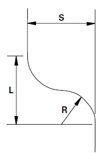
You may use the following formula to determine the minimum distance necessary for permanent cable training (offset bending) in a manhole:
____________
L = √ S (4 R – S)
Where:
L = Minimum distance required (in)
S = Offset (in)
R = Bending radius to cable centerline (in)
 Allow a suitable length of straight cable at both ends of the offset bend.
Power and Control Cables without Metallic Shielding or Armor
|
Insulation |
Overall Diameter of Cable |
||
| 1.000 and Less | 1.00 to 2.000 | 2.001 and Over | |
| Minimum Bending Radius as a Multiple of Cable Diameter | |||
| 155 and less | 4 | 5 | 6 |
| 156 to 310 | 5 | 6 | 7 |
| 310 and over | - | 7 | 8 |
Note 1: The highest applicable multiplier should be used in all cases. The calculated minimum bend radius (applicable multiplier x outside diameter of cable) refers to the inner surface of the bent cable, and not the axis (centerline) of the cable conduit.
Note 2: Use the thickest of the insulations of the cables within the assembly and the diameter of the largest single cable within the cable assembly to determine the multiplier. Afterwards, apply that multiplier to the diameter of the overall assembly.
Note 3: The minimum values for the radii to which cables may be bent during installation may not apply to conduit bends, sheaves or other curved surfaces around which the cable may be pulled under tension while being installed. Larger radii bends may be required for such conditions. (Please reference “Precautions during Cable Pulling” in the “Sidewall Bearing Pressure” section).
Power and Control Cables with Metallic Shielding or Armor
| Cable Type | Minimum Bending Radius For Single Conductors |
Minimum Bending Radius For Multiple Conductors† |
| Interlocked and Polymeric Armor (without shielded conductor) |
7 |
7 |
| Interlocked Armor and Polymeric Armor (with shielded conductor) |
12 | 7 |
| Wired Armored Cable | 12 | 12 |
| Metallic Tape Shielded Cable | 12 | 7 |
| Metallic Fine Wire Shield | 12 | 7 |
| Concentric Neutral Wire Shielded Cable | 8 | 5 |
| Lead Sheath Cable | 12 | 7 |
| LC Shielded Cable | 12* | 7 |
† Use the larger of the two minimum bending radii when considering the minimum-bending radius for multiple conductors.
*For conductor sizes 1500kcm and larger, the minimum bending radius for LC Shielded cable is 18X the cable diameter.
Note 1: Multiply the diameter of the cable by the factor in the table above to attain the minimum-bending radius.
Note 2: These limits may not be appropriate for use with conduit bends, sheaves or other curved surfaces around which the cable may be pulled under tension while being installed due to sidewall bearing pressure limits. The minimum radius specified refers to the inner radius of the cable bend and not to the axis of the cable.
Clearing Ducts
Using a plug that is roughly the same diameter as the inside of the duct does not permit obstructions in the duct since it pulls the plug through the structure. After doing this, use a wire brush to clean and remove foreign matter from the duct. In order to prevent scratch damage to the cable jacket during pulling, it is important to smooth the interior.
Trench for Direct Burial
To prevent damage to the cable jacket during or after cable installation, the trench should be clean of sharp stone, glass, metal or wood debris. The trench bottom should be evenly covered with a layer of soil or sand that has been screened through a medium-to-fine mesh screen to remove all larger stones or other material. This will assure a smooth, soft-bedding surface for the cable(s). It is a good idea to lay a protective covering on the fill about 6-8 inches above the cable to protect it if working in an urban area or near where a lot of digging occurs. If working under highways or railroad right-of-way, it is also a good idea to install the cable in a pipe or conduit to give added mechanical protection.
Rack/Trays
One should check the entire path that the cable will follow during pulling to make sure that the cable will have a smooth ride, free of all barriers or sharp edges. In checking this, one should consider the position the cable will take on when under tension.
(continued...)
