2980 NE 207th Street | Suite PH
Miami, FL 33180
Toll-Free: 800.342.7215 (US and Canada only)
Phone: 954.455.3050
Fax: 954.455.9886
Email: sales@buyawg.com

Special Conditions for Metallic Armored Cables
Sheath Currents and Voltages in Single Conductor Cables
A voltage is induced in the concentrically applied wires of the grounding conductor and the armor in a single conductor cable with an interlocking armor.
A current will flow in the completed path if the armor and the concentric grounding conductor are bonded or grounded at more than one (1) point. The magnitude of the induced voltage is relative to the magnitude of the current in the phase conductor. The magnitude of the sheath currents is a function of the induced voltage and the sheath impedance. The armor and the grounding conductor can become very hot if the sheath current is large. If this occurs, the conductor insulation will also be subjected to temperatures that may cause electrical failure or reduce the life expectancy of the cable.
One will have to derate the cable if sheath currents are large enough to raise the temperature of the insulation above its rated value.
In a single conductor cable carrying currents less than 180 amps, sheath currents will not pose a problem since induced voltages and sheath impedances minimize sheath losses.
In single conductor cables carrying currents between 180 and 425 amps, sheath currents will not pose a problem if the cables are spaced about one (1) cable diameter apart. When this spacing is done, mutual heating is minimized and the induced voltage is reduced by virtue of field cancellation.
In single conductor cables carrying currents larger than 425 amps, it is normally necessary to derate the cables to avoid overheating unless the sheath currents are removed.
Armor of magnetic material (such as galvanized steel) should not be used on single conductor cables intended for use in AC circuits.
Eliminating Sheath Currents
One needs to make sure that all paths by which sheath currents circulate are kept open in order to prevent the current from flowing.
One should ground and bond cable armors and concentrically applied grounding conductors at the supply end only and afterwards isolated from ground and each other. Isolation may be established when installing cables in individual ducts by using cables with PVC jackets or other insulating materials, or also by mounting cables.
No sheath current will flow if the armors and concentrically applied grounding conductors are bonded and grounded at the supply end through a non-ferrous metal panel and mounted on an insulated panel at the load end. For an illustration of this, please see the figure down below.
a) Cables enter supply end enclosure through metallic non-ferrous panel to avoid overheating. Cable armors are bonded through panel.
b) Cable enters load end enclosure through panel of insulating material. The insulating material maintains the open circuit of the armors.
c) Cable armors and concentrically applied grounding conductors are bonded and grounded at the supply end only. When installed in this way, the armor and concentric grounding conductor do not form a part of the system ground circuit and a separate ground conductor should be installed, following the proper electrical code.
d) All cable connectors and lock nuts are made of non-magnetic metal (aluminum or other).
Standing Voltage
An induced voltage will exist between ground and both the armor and the concentric grounding conductor throughout the length of the cable when single conductor cables are installed, as shown in the figure below:

The magnitude of this voltage is proportional to the phase conductor current, the cable length and the spacing between the cables. The magnitude of the “standing voltage” is usually limited to about 25 volts. Please be aware that some Electrical Inspection Authorities limit this voltage to a lower amount.
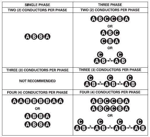
By grounding the armor and the concentric grounding conductor at the midpoint of the cable run, one can limit the standing voltage and also increase the circuit length. If doing this, the cable must go through a junction box at the midpoint of the run and must be connected on each side of the junction box as shown on the supply end of the figure above. In this case, the cables at both the supply and load ends must be connected through panels of insulating material to prevent the flow of sheath currents. Nevertheless, when two (2) or more single conductor cables are installed in parallel per phase, grounding at the midpoint is not allowed. For more on installing single conductor armor cables in parallel please see the diagram below, which depicts symmetrical configurations:

Notes:
1. S = Separation of groups. This equals the width of one group.
2. Horizontal and vertical separation between adjacent cables should be a minimum of one (1) cable diameter to benefit from the ampacity in free air in a ventilated cable tray.
3. Neutral conductors can be located outside of the above groups.