2980 NE 207th Street | Suite PH
Miami, FL 33180
Toll-Free: 800.342.7215 (US and Canada only)
Phone: 954.455.3050
Fax: 954.455.9886
Email: sales@buyawg.com

Applications:
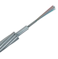
OPGW cable is suited for installation on transmission lines with the double function of a ground wire (designed to replace traditional static or shield wires) and a communication wire. OPGW conducts short circuit current and provide lightning resistance as it “shields” conductors, while providing a telecommunications path for internal as well as third party communications. OPGW must be capable of withstanding the mechanical and environmental stresses inflicted on overhead cables (such those caused by wind or ice). OPGW must also be capable of handling electrical faults on the transmission line by providing a path to ground yet preventing damage to the delicate optical fibers inside the cable.
OPGW (Optical Ground Wire) with a stainless steel central tube is preferred for its compact size and ability to house up to 72 fibers in a diameter starting at only 12mm. Its small profile offers an exceptional solution to the diameter and weight concerns on many of today’s overloaded transmission towers where an existing shield wire needs to be replaced with an OPGW cable.
Construction
OPGW cable has two constructions:
Central loose tube type---The fibers are placed loosely in a sealed and water resistant central, aluminum tube filled with water blocking gel. This tube provides protection to the fiber during installation and operation under severe environmental conditions. The stainless steel tube may also be aluminum-clad steel depending on the engineering requirements. The stainless optical tube is located at the center of the cable protected by single or multiple layers of aluminum clad steel, aluminum alloy wires, or steel wires. The metallic wires provide mechanical strength to withstand severe installation and operating conditions, while achieving conductivity to control temperature rise during short circuit conditions.
Each optical fiber is clearly distinguishable utilizing a fiber identification system consisting of coloring and the number of ring marks on it. This compact design features high mechanical strength and fault current rating within a smaller diameter. The smaller diameter also results in excellent sag tension performance.
Multi loose tube type--- The fibers is placed loosely in a sealed and water resistant stainless steel tube filled with water blocking gel. Two or three stainless steel optical tubes are helically stranded in the inner layer of a multiple-layer cable. The multi loose tube type is designed mostly for very high fiber count requirement over 48 with the maximum fiber count reaching 144. The multi loose tube type can meet the requirement of huge cross and large current capacity.
The optical fiber is made of high pure silica and germanium doped silica. UV curable acrylate material is applied over fiber cladding as optical fiber primary protective coating. The detail data of optical fiber performance are shown in the following table.
Optical fiber uses special spun device successfully controlled the value of PMD, and makes sure that it can keep stable in cabling
Standards
Options
Notes

Item # |
FIBERS |
FAULT
|
TOTAL
|
TOTAL
|
OVERALL
|
OVERALL
|
WEIGHT
|
Weight
|
RBS
|
RBS
|
|---|---|---|---|---|---|---|---|---|---|---|
| OPGW-2S 1/24 (M85/R77-51) | N/A 24 | N/A 51 | N/A 0.1273 | N/A 85.05 | N/A 0.484 | N/A 12.3 | N/A 0.321 | N/A 0.478 | N/A 17390 | N/A 7888 |
| OPGW-2S 2/18 (M80/R72-46) | N/A 36 | N/A 46 | N/A 0.1202 | N/A 80.34 | N/A 0.484 | N/A 12.3 | N/A 0.313 | N/A 0.466 | N/A 16107 | N/A 7306 |
| OPGW-2S 1/24 (M107/R76-97) | N/A 24 | N/A 97 | N/A 0.1603 | N/A 107.13 | N/A 0.544 | N/A 13.8 | N/A 0.338 | N/A 0.503 | N/A 16984 | N/A 7704 |
| OPGW-2S 1/24 (M115/R69-121) | N/A 24 | N/A 121 | N/A 0.1722 | N/A 115.05 | N/A 0.563 | N/A 14.3 | N/A 0.328 | N/A 0.488 | N/A 15611 | N/A 7081 |
| OPGW-2S 2/48 (M137/R107-147) | N/A 96 | N/A 147 | N/A 0.2046 | N/A 136.72 | N/A 0.630 | N/A 16 | N/A 0.472 | N/A 0.702 | N/A 24048 | N/A 10908 |
| OPGW-2S 2/48 (M137/R100-154) | N/A 96 | N/A 154 | N/A 0.2046 | N/A 136.72 | N/A 0.630 | N/A 16 | N/A 0.450 | N/A 0.67 | N/A 22384 | N/A 10153 |
| OPGW-2S 2/48 (M150/R107-186) | N/A 96 | N/A 186 | N/A 0.2246 | N/A 150.11 | N/A 0.662 | N/A 16.8 | N/A 0.499 | N/A 0.742 | N/A 24183 | N/A 10969 |
| OPGW-2S 3/48 (M129/R97-134) | N/A 144 | N/A 134 | N/A 0.1926 | N/A 128.68 | N/A 0.630 | N/A 16 | N/A 0.449 | N/A 0.668 | N/A 21865 | N/A 9918 |
| OPGW-2S 3/48 (M129/R98-134) | N/A 144 | N/A 134 | N/A 0.1926 | N/A 128.68 | N/A 0.630 | N/A 16 | N/A 0.449 | N/A 0.668 | N/A 21934 | N/A 9949 |
| OPGW-2S 3/48 (M141/R105-161) | N/A 144 | N/A 161 | N/A 0.2114 | N/A 141.29 | N/A 0.662 | N/A 16.8 | N/A 0.499 | N/A 0.743 | N/A 23598 | N/A 10704 |